next up previous contents
Next: 4.4 Self-organization of lateral Up: 4 Training the Orientation Previous: 4.2 Training parameters

4.3 Receptive fields and orientation maps

  The self-organization of afferent weights results in oriented synaptic weight patterns forming afferent receptive fields. Figure 4.2 shows examples of these weight patterns plotted on the retinal surface for several neurons.
 
Figure 4.2: Self-organization of afferent receptive fields.
  The afferent weights to three neurons near the center of the cortex are shown, plotted on the retinal surface. The top row shows the initial afferent weights for each neuron, and the bottom shows the weights after self-organization (at iteration 30,000). Initially, all of the neurons had random afferent weights across the anatomical receptive field area, and were not selective for orientation. Through self-organization, the first two neurons became highly selective for a particular orientation. The third became selective for retinal position within its RF, but remained unselective for orientation; this type of RF is relatively rare in V1 as well as in the model. When a Gaussian input of a particular orientation is presented at the location of these receptive fields, the first neuron will fire strongly only if the Gaussian is oriented near +45°, since otherwise very little of its receptive field will be activated. Similarly, the second neuron will fire for a Gaussian oriented near -30°, while the third will have approximately equal response to all orientations. These types of receptive fields have also been found in the cortex, and serve to encode the local orientation at that position on the retina.
\begin{figure}
\begin{minipage}
{\textwidth}
 \centering
 \begin{minipage}
{\thr...
 ...vspace{0.5\baselineskip}\newline
\usebox {\orkey}

 \end{minipage}
 \end{figure}

A variety of such RFs are produced in the self-organizing process, most highly selective to inputs of a particular orientation, others unselective.

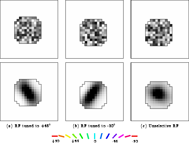
To show how the orientation preferences are located across the network, an orientation map was computed by labeling each neuron with its orientation preference, as determined from its afferent weights. The afferent weights were fitted to an ellipsoidal Gaussian (equation 4.1) using the nonlinear programming package NPSOL (Gill et al., 1986). The orientation of the fitted function was taken to be the orientation preference of that neuron; it is the orientation of the Gaussian that maximally excites the afferent weights. Because the receptive fields were themselves developed based on Gaussian inputs, their orientation preferences were generally unambiguous, and other methods of computing the orientation map would show very similar results.

Figure 4.3 shows the global organization of the receptive fields in the network before and after training.
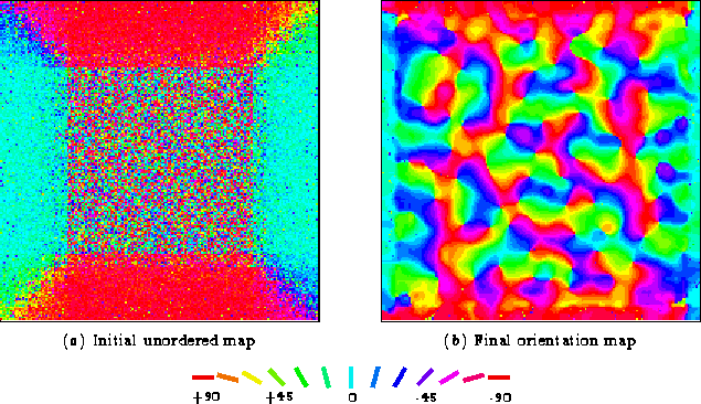
 
Figure 4.3: Self-organization of the orientation map.
  Each neuron in these plots of the cortex is colored according to the orientation preference of its afferent weights (as shown on the key.) (a) Initially, the afferent weights are random within a fixed receptive field. However, near the borders the receptive fields are elongated in shape because they are cut by the edge of the retina. This gives neurons near the edge an initially oriented receptive field, even though the weights themselves are random. (b) After 30,000 input presentations, the receptive fields organize into continuous and highly selective bands of orientation columns. Near the borders, the patterns have seamlessly self-organized in a way that takes advantage of the bias towards receptive fields parallel to the borders. It is not known whether such edge effects occur in biological systems, where only central regions have been studied in detail. The central section of the map is both qualitatively and quantitatively similar to those found in the macaque monkey (Sirosh, 1995). Both include (1) pinwheels, points around which the orientation preferences change continuously (e.g. just below and to the left of the center of the cortex) (2) linear zones, bands where the orientation preferences change continuously, like a rainbow (e.g. from just below the center, down to the left at a 30° angle from vertical), and (3) fractures, regions where the orientation preference changes abruptly between two distant orientations (e.g. almost half-way over from the center to the left, between the red and green areas).
\begin{figure}
\begin{minipage}
{\textwidth}
 \centering
 \begin{minipage}
{\two...
 ...\baselineskip}\newline
\usebox {\orkey}

 \end{minipage} \newline

 \end{figure}

The color of each neuron indicates its orientation preference as indicated in the key. Initially, all the afferent weights are random. As a result, the orientation preferences of the RFs are random and most RFs do not have a strong preference for any particular orientation. As self-organization progresses and afferent weights develop oriented receptive fields like those in figure 4.2, a complex organization of orientation preferences develops. The map is remarkably similar in structure to those observed in the primary visual cortex by recent imaging techniques (Blasdel and Salama, 1986; Blasdel, 1992b), and contains complicated structures such as pinwheels, fractures and linear zones.[*] The results suggest that Hebbian self-organization of afferent weights, based on recurrent lateral interactions, could underlie the development of orientation maps in the cortex.


next up previous contents
Next: 4.4 Self-organization of lateral Up: 4 Training the Orientation Previous: 4.2 Training parameters
James A. Bednar
9/19/1997